6.14 Former Naval Weapons Industrial Reserve Plant, McGregor, Texas
The former Naval Weapons Industrial Reserve Plant (NWIRP) is in McGregor, Texas, which is 20 miles west of Waco, Texas. Before closure in 1995, the facility consisted of isolated industrial sites located on 9,700 acres. Over its history, the facility transitioned from bomb manufacturing in the 1940s to rocket motor development and testing from the 1950s until closure.
VOCs such as TCE and 1,1,1-trichloroethane (1,1,1-TCA) were used as solvents and released into the environment at some of the industrial sites. In addition, ammonium perchlorate, a chemical oxidizer used in rocket motor engines, became an emerging contaminant at the time of the facility’s closure. This case study focuses on ammonium perchlorate because it is the main risk driver at the site.
Ammonium perchlorate quickly disassociates when it comes in contact with water. The ammonia is taken up by plants, and the perchlorate anion is conservative and does not degrade under the naturally aerobic aquifer conditions found at the site. Because of perchlorate’s fate and transport characteristics, it can pass through the thin soil cover at the site and enter the 20 to 30-foot thick upper water-bearing zone of weathered limestone. The site’s groundwater hydraulic gradient parallels the topography through secondary porosity features, such as fractures, small solution cavities, and bedding planes. When groundwater elevations are high during the wetter parts of the year, perchlorate contaminated groundwater can surface along hillside springs, tributaries, and streams. When perchlorate enters the surface water regime, its travel time increases until it encounters a losing stream segment. These leaps in travel time, called a “porpoising effect” has created thin plumes in three separate drainage basin miles downstream from the facility’s boundary (Figure 61).
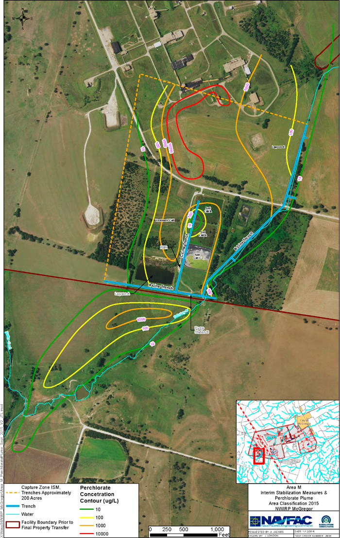
Figure 61. McGregor site drainage basins (NAVFAC SE, 2016).
Ultimately the remedial investigations expanded to approximately 22,000 acres before the plumes were fully delineated to the protective concentration levels (PCLs) that the state of Texas established for Class 2 Groundwater Resource (17 µg/L, residential, and 51 µg/L, commercial/industrial). The VOC plumes are colocated within the perchlorate plume, however, their footprints have remained on site and within or adjacent to the industrial complexes.
6.14.1 Technical Basis for Remedial Action (Characterization/CSM)
In the 1990s, perchlorate was identified as an emerging contaminant by USEPA and NWIRP McGregor was listed as a facility that used ammonium perchlorate in the production of rocket motors. In 1998, the Texas Natural Resource Commission, now the Texas Commission of Environmental Quality (TCEQ), instructed the Navy to begin investigating environmental media at the site for evidence of perchlorate contamination. Perchlorate was detected in three drainage basins at the former NWIRP McGregor facility.
In 1999, bench scale studies were conducted to determine the best approach for remediating perchlorate in the geologic and hydrogeologic environments found at the site. Anaerobic biological degradation was selected as the best remediation approach. Two biological systems were designed, one active and one passive. The active system, located in the southwest drainage basin where the highest perchlorate concentrations were found, came on line in 2002 and consisted of the following:
- three cutoff trenches (totaling approximately 6,000 feet) keyed into a non-water- bearing zone 15 to 25 feet below ground surface and 3 feet wide
- a 400 gpm capacity anaerobic fluidized bed reactor (FBR)
- storage lagoons within the footprint of the cutoff trenches capable of managing approximately 16 million gallons of water
- a permitted discharge outfall when needed (Figure 62).
As of 2014, the system has processed and degraded approximately 70% of the 8,200 pounds of perchlorate mass originally thought to be present in the shallow water bearing zone within the 200-acre footprint of the cutoff trenches (Figure 63).
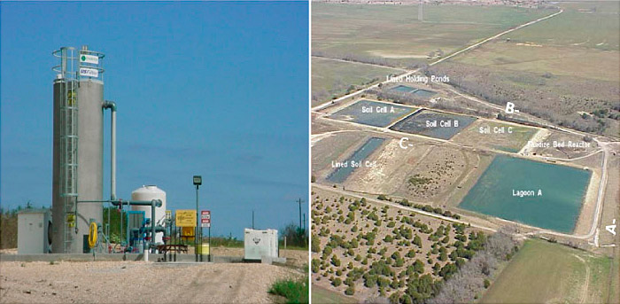
Figure 62. Fluidized bed reactor (FBR) on the left and treatment system components and water management system on the right (NAVFAC SE, 2016).
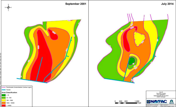
Figure 63. Estimated plume mass in 2001 (8,200 lbs) and in 2014 (2,600 lbs) (NAVFAC SE, 2016).
Water storage is managed through a combination of reinfiltration, evaporation, and active discharge. Groundwater elevation in the trenches is maintained to prevent perchlorate-contaminated groundwater from discharging into surface water.
Because the 1999 pilot studies demonstrated that perchlorate degraded almost instantaneously when the groundwater was exposed to anaerobic conditions, the Navy decided to use an innovative passive remedial approach in the northeastern and southeastern drainage basins where lower perchlorate concentrations plumes had been delineated. The NWIRP McGregor project team agreed to this approach and remedial action plans were developed with the provision that the passive system and associated plumes be monitored under a long-term monitoring (LTM) groundwater program. In areas of low topographic relief, the passive system consisted of segmented 3-foot wide trenches keyed into the non-water bearing zone. The trenches (called “biowalls”) were filled with a mixture of gravel combined with wood chips and mushroom compost soaked in vegetable oil. The trench design included piping that would allow emulsified oil to be injected when necessary to rejuvenate the carbon content so the localized anaerobic conditions could be maintained. This passive system consisted of 35 segments ranging in length from 42 feet to 1,000 feet; in all, approximately 11,200 feet of biowalls were constructed between 2002 and 2005. In areas where topographical relief was steeper and the biowall seeps were likely, the passive system consisted of three staggered lines of 12-inch borings (bioborings) keyed into the non-water-bearing zone. Once drilled, the bioborings were filled with the same mixture of gravel with wood chips and mushroom compost soaked in vegetable oil to create a localized anaerobic zone. Unlike the first generation of bioborings, a second generation of bioborings are being designed with piping to allow emulsified oil to be injected when necessary. Because of these efforts, the distal parts of the perchlorate plumes have receded towards the former facility.
6.14.2 Monitoring/Optimization
16.14.2.1 Monitoring
O&M of the FBR, biowalls, and LTM have been ongoing since 2002. Because the facility is closed, operation of the FBR is performed remotely through an internet portal that is checked twice daily and through site visits twice a week. If an operational issue develops while no one is on site, the system is designed to automatically send out an alarm to the operator. Depending on the situation, the operator may be able to solve the issue via the portal or, if need be, make an unscheduled trip to the site for repairs. During weekly visits, influent and effluent samples are collected and the system is inspected.
The FBR maintains biological reducing conditions through a chemical feed system that is regulated continually according to influent flow and perchlorate and nitrate concentrations. The main chemical carbon source is 6% acetic acid. Effluent water can be directed to the various holding lagoons, where it can be stored for evaporation and/or discharge through a permitted outfall.
Water samples are collected from ports in the biowalls on a semiannual basis along with field measurements. Effectiveness is monitored through the following screening parameters that are scaled and then added to determine if carbon replenishment is required:
- total organic carbon
- nitrate
- methane
- oxidation-reduction potential
- perchlorate
Carbon is replenished by mixing emulsified oil and water, then transporting the mixture to the injection ports by trailer. The mixture is then pumped into the biowall.
During the remedial investigations and evaluation of groundwater, approximately 800 monitoring wells were installed across the former facility and on off-site property. In 2006, when the LTM program was initiated, the number of active monitoring wells that were to be used to monitor the effectiveness of the remedial program was approximately 160; the rest had been abandoned. The LTM program consists of an annual sampling with a few select wells sampled on a semiannual basis. The analytical suite performed on each well is perchlorate, VOCs, or a combination of the two. Results from the monitoring are reported to TCEQ and USEPA on a biennial basis. The number of wells currently being monitored has been reduced to approximately 100 wells through optimization of the long-term management monitoring program. The elimination of monitoring wells is a good indication that remedial systems remain effective and that the size of the groundwater plumes are decreasing.
6.14.2.2 Optimization
The Navy has embarked on a holistic optimization program consisting of the following three elements:
- Transition the FBR, the cutoff trenches, and water storage management structures to a remediation system consisting of combination biowalls and bioborings in the southwestern plume area.
- Reevaluate Groundwater Resource Classification based on data collected during remedial activities with the goal of changing the Resource Classification from Class 2 to Class 3. If approved, the PCL screening values will be raised by a factor of 100 (perchlorate residential screening PCL value would be 1,700 µg/L and commercial/industrial value PCL 5,100 µg/L).
- Reevaluate the groundwater to surface water migration pathway in regards to dilution factors that will influence perchlorate concentrations before becoming a risk to human health and the environment.
6.14.2.3 Status of the Optimization Program
The FBR will remain online during a transition period while evaluations of other remediation systems (including pilot tested biowalls) are evaluated. A set of second generation bioborings are scheduled to be installed in parts of the southwestern plume area the first quarter of 2016. The goal is to reduce perchlorate concentrations before groundwater enters the cutoff trenches and is processed through the FBR. If successful, this action will reduce O&M costs.
A technical memorandum has been submitted to TCEQ and USEPA presenting groundwater hydrogeologic data collected during remedial activities. The team has since approved the recommendation to change the Groundwater Class Resource from Class 2 to Class 3. A dilution study was conducted during a 6 month period from April through September 2015. The data have been processed and will be presented to TCEQ and USEPA for evaluation.
6.14.3 Regulatory Involvement
The Navy, TCEQ, and USEPA are working closely together to institute an innovative, cost-effective, and multifunctional approach to remediating perchlorate and VOCs. Future optimization planning will continue to focus on innovative passive methods to treat perchlorate in groundwater, and institutional controls to ultimately phase out the FBR system and bring the site to closure.

